Timing LED.
Most performance ignition modules have a Timing LED. This can be used
for static timing and as a diagnostic aid. The LED should light up when
the ignition key is turned on. The timing LED will go off when the
crankshaft is rotated past TDC. During cranking the LED will blink.
TIMING PROCEDURE
For most 1984 and later models, most aftermarket ignition system
installation does not require resetting the ignition timing. For earlier
models where a new trigger rotor or camshaft position sensor is installed,
you must reset the timing.
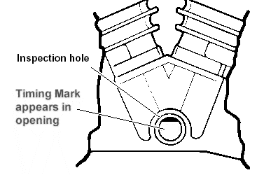
The TDC and advance timing marks are located on the fly-wheel and can
be observed via an inspection hole (refer to the shop manual for details).
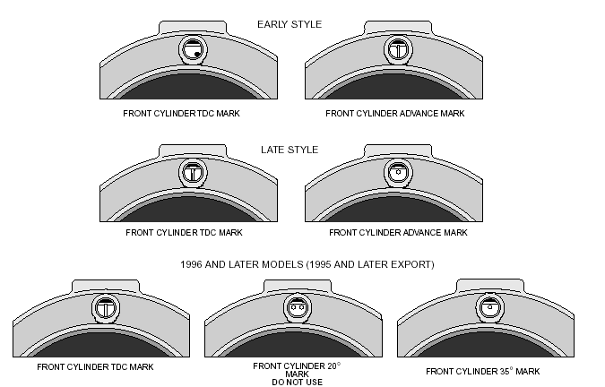
Refer to Figure 1 for typical timing marks. Early
Style includes most 1980 and earlier models. Late Style includes most
1981-95 models. If the shop manual is not available, remove spark
plugs, turn engine until front piston is at TDC on compression stroke and
identify TDC mark on the flywheel. Refer to Figure
0 and find the diagram with a matching TDC mark. Use the corresponding
advance mark shown in the diagram.
INITIAL STATIC TIMING PROCEDURE
If the engine will not start or runs very rough, you can use the
following static timing procedure. Remove spark plugs and turn engine
until TDC mark appears in observation hole. Ground spark plugs with an
alligator clip so you will not shock yourself.
Turn on ignition. Loosen the standoffs holding camshaft position sensor
and rotate it clockwise until timing LED goes out. The point at which LED
goes off is TDC. Timing is now set approximately at TDC, which is correct
for cranking conditions.
Turn off ignition and reinstall spark plugs.
ADVANCE TIMING PROCEDURE - USING STANDARD TIMING LIGHT
This timing procedure requires that a VOES switch be connected to the
ignition module. For racing applications without a VOES switch,
you must ground the VOES input (purple/white wire) while setting
the timing. Connect a timing light to the front cylinder. Set the
ignition module advance slope switch to midrange. Run the engine at 2,400
to 2,500 RPM. Rotate camshaft position sensor until advance timing mark is
centered in the observation hole. Tighten the standoffs and verify that
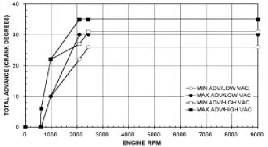
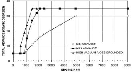
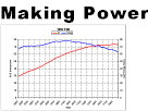
timing has not shifted. Timing will now correspond to the curves in
Figures 5 or 6.
SETTING PRECISE ADVANCE TIMING FOR RACING
USING DIAL BACK TIMING LIGHT
Determine the advance you want at 2,500 RPM. Use a dial-back timing
light. Set the amount of advance you want, say 35 degrees, on the
dial-back timing light. Connect the dial-back timing light to the front
cylinder. If the VOES is used, disconnect the VOES input (purple/white
wire) while setting the timing with this procedure. Set the ignition
module advance slope switch for maximum advance. Run the engine at 2,500
RPM. Rotate camshaft position sensor until TDC timing mark is centered in
the observation hole. You will now have the amount of advance you dialed
into the timing light. Tighten the standoffs and verify that timing has
not shifted. Some dial-back timing lights are not compatible with odd
firing H-D ® V twin engines. Most Sears units are OK. Snap-On units may
not function correctly.
TROUBLESHOOTING
Did the engine run properly before installation of the ignition module?
If not, remove the ignition module, reinstall the OEM ignition or another
known good unit and then find and correct the original problem.
Did the ignition module function correctly before the problem occurred?
If the answer is yes, did you change anything that may have affected it?
Try going back to the last setup that worked OK to help isolate the
problem.
If the engine will not start, or runs rough or intermittently, use the
following checklist steps:
ENGINE WILL NOT START
Check that timing LED lights up when ignition key is first turned on.
If not, check for +12 volts on white wire to COIL+.
Check that timing LED blinks while engine is cranked. If not, camshaft
position sensor or ignition module may be defective.
If the timing LED blinks, but engine will not start, recheck all wire
harness connections or replace coil(s).
NOTE: Applicable to single fire mode only. Most dial-back timing
lights will not work correctly in dual fire mode.
NOTE: 1996 and later models (1995 and later for export models)
have a timing mark at 20° BTDC for setting the timing with the O.E.
ignition module. Do not use this mark for setting the timing with
the ignition module. In most cases an additional mark will remain at 35°
BTDC (see Figure 7). Use this mark to set the timing with a timing
light as described below.
Check for low voltage from a faulty or marginal charging system
and battery.
CHECKING FOR SPARK
To crank the engine and check for spark, use a KD Tools test
plug or H-D tool HD-26792.
These test plugs come with an alligator clip that must be
attached to frame or engine ground. Use a length of spark
plug wire to connect the test plug to the coil.
MISFIRE OR INTERMITTENT OPERATION
Field experience has shown that popping back through the
carburetor, misfiring, and intermittent failure (especially after
the engine gets hot) are usually not caused by electrical
problems within the ignition module. Carburetor problems, fouled
spark plugs, coil failure, and loose wire harness connections
are the most common culprits.
Verify that spiral core or suppression type spark plug wires and
resistor spark plugs are being used.
TACH INOPERATIVE
If the tach is inoperative after installation of the
ignition in single fire mode, you may require a tach adapter.
Most ignition module tach output is compatible with ground
sensing tachs which includes most O.E. and aftermarket
tachs. Some tachs require a high voltage trigger pulse.
In this case, install a Crane tach adapter P/N
8-2050.
Damage to the ignition module circuitry may have occurred if 12
volts was applied to the tach wire at any time.